INTRODUCTION
The Stewart Mountain Dam located 41 miles (66 km) east of Phoenix,
Ariz., on the Salt River, was completed in March 1930. The structure contains
an arch dam, two thrust blocks for simulating abutments for the arch dam,
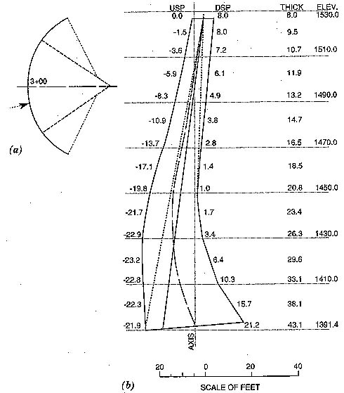
three gravity dams, and two spillways. The arch dam measures 212 ft (64.6
m) high at the maximum section, 8 ft (2.44 m) thick across the crest, 34
ft (10.36 m) thick across the base, and 583 ft (177.7 m) in length along
the crest. Four keyed vertical contraction joints with copper water-stops
separate the arch into distinct concrete sections called cantilevers. The
concrete structure has experienced alkali-silica reactions and has exhibited
no bond across horizontal construction lift surfaces. In addition, the
dam could be subjected to upgraded maximum credible earthquake (MCE) or
probable maximum flood (PMF) loadings.
Numerous investigations, field measurements, laboratory test, inspection, and on-site tests have been performed over the years to assess material properties, deformation, and deterioration. Concrete cores were extracted in 1943, 1946, 1947, 1948, 1968, 1977, 1979, 1982, and 1985. The many engineering questions that arose during the investigations and inspections included the following: (1) What caused the poor lift surface bond and what was its extent?; (2) What is the serviceability life expectancy of the existing or deteriorating concrete?; (3) At what rates are the alkali-silica reactions deteriorating the concrete? Have the reactions stopped? Could changing reservoir levels or other conditions accelerate the reaction?; (4) is the concrete more brittle due to micro-fracturing from the reactions?; (5) Why does the upper arch appear more susceptible to the alkali-silica reactions than other areas of the dam?; and (6) Why do deflection measurements of the crest indicate a slowing or stopping of the rate of permanent drift toward the up-stream direction?
Comprehensive investigations of Steward Mountain Dam revealed that alkali-silica reactions and expansions have caused visible surface cracking. Engineering appraisals predict small amounts of future reactions relative to the past based upon deflection measurements at the crest, petrographic analysis, laboratory expansion tests, and reviews. The crest of the dam has permanently displaced about 6 in. (15.24 cm) upstream since 1937; however, displacement has been very minor since 1964. Expansion tests on extracted core in a fog room and in a sodium hydroxide solution showed very little formation of new gel or expansions. The amount of available soluble alkali needed for continued reaction is negligible or limited. The interior concrete is relatively unaffected and therefor could have many more years of continued serviceable life expectancy.
Also revealed, lower temperatures deep in the reservoir and deep within the concrete, higher leaching of available reaction gel into capillary space, and different cements have caused less than usual alkali-aggregate reaction in the lower arch. Also, poor bonding across horizontal lift surfaces is due to the formation of laitance from severe bleeding of high-water-content concrete on the top of each lift. Construction practices in 1930 did not recognize the importance of cleaning construction joints before subsequent concrete placements. The poor bond, therefore, extends throughout the arch.
MATERIAL PROPERTIES
Compressive Strength
The average value of uni-axial concrete compressive strength from 6-in.
(15.2-cm) cores ranges from a low of 3,867 lb/sq in. (37.21 kPa) obtained
in 1985. This wide range is in fact a function of where the core was extracted.
Cores before 1950 were drilled from the roadway deck and downstream fsace
areas, which exhibited more alkali-aggregate reaction. Cores after 1950
were drilled vertically through the arch into the interior of the dam,
and indicated relatively strong concrete. Uni-axial concrete compressive
strengths averaged over 6,000 lb/sq in. (41.34 kPa) in the thrust blocks
and gravity sections.
Tensile Strength
Splitting tension and direct tension tests on 6-in. (15.2 cm) concrete
cores were performed in 1985, 1983, and 1968. Splitting-tension strengths
were approximately 7-10% of the compressive strength; direct tensions were
much less, at approximately 1-3%. These results were similar to those reported
by Raphael (1984).
Modulus of Elasticity
Modulus of elasticity is a good indicator of the strength or deterioration
in concrete. The average modulus values from 6-in. (15.2 cm) cores ranged
from 2,890,000 lb/sq in. (19.91 MPa) ihn 1943 to 3,590,000 lb/sq in. (24.74
MPa) in 1985. This range of modulus also indicates differences between
interior and exterior concrete. Modulus values were plotted and contoured
over the entire downstream profile of the arch dam in an attempt to visualize
weak zones. No definite patters were established.
Thermal Properties
Thermal properties were obtained by comparing tests on concretes with
similar aggregate. Comparisons indicated a thermal diffusivity of 0.45
sq ft/hr (4.18 m2/h) and a coefficient of thermal expansion
of 0.00005 in./in./degrees R (0.00000m/m/degrees C).
Shear Strength
Shear capacity of the arch dam was greatly affected by construction
practices. Laitance remains on horizontal lift surfaces essentially eliminate
cohesion between subsequent blocks. A concrete core taken in 1985 showed
that out of 16 horizontal lift surfaces there were 13 that were unbonded.
Thrust-block coring in 1979 found that all lift surfaces were unbonded.
Foundation
Foundation strength greatly influences stress distribution within an
arch dam. A weak foundation redirects more load into the arch and less
around the abutment contact than a strong foundation. The foundation is
Precambrian quartz diorite intruded by irregular dikes of granite (unpublished
Bureau of Reclamation files 1930-90). The site contains two faults, designated
as the tailrace and spillway faults. The tailrace fault passes under the
arch near the maximum vertical section. Extensive geological investigations
were performed at the site, including surface surveys, foundation coring,
down hole geophysics and laboratory tests.
LITERATURE REVIEW
Many dams built before 1945 and located in the southwestern United
States, such as the Coolidge, Stewart Mountain, and Parker dams in Arizona
and the Riant and Matilija dams in California, have shown signs of alkali-silica
reactivity in the concrete. The Matilija Dam showed permanent displacement
upstream at the crest ("Railroad" 1984), with concrete cores indicating
alkali-silica reactions and deterioration in the uper 25 ft (7.6 m). Modifications
made to the Matilija Dam included notching and enlarging the spillway.
The Railroad Canyon Dam in southern California has similar horizontal lift
surface bond problems (Matilija 1972). The dam, completed in 1928, consists
of an arch dam portion with supporting thrust blocks. The dam was stabilized
by placing additional concrete on the thrust blocks and installing six
200 kips (890 kN) post-tensioned cables in each abutment.
LOADING CONDITIONS
Normal operating loads - The structure of the Stewart Mountain Dam
was analyzed for gravity-, reservoir-, temperature-, and earthquake-induced
loads. Gravity loads were investigated by considering the stage construction
sequence of concrete placement. The secondary stresses were very small.
Temperature-induced loads included considerations for ambient air temperatures,
reservoir temperatures, concrete diffusivity, solar radiation, terrain
factors, stress free temperature, and concrete thickness.
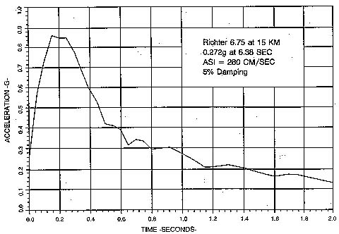
Seismic loads - Extensive seismo-tectonic studies were performed for the site identifying the controlling MCE as a Richter magnitude 6.75 at 15 km from the Sugarloaf Fault ("Seismo-tectonic" 1986). A peak ground acceleration of 0.34 g was predicted from attenuation curves developed from historic records on rock sites (Seed and Idriss 1982). Historic and synthetic accelerograms scaled by the acceleration spectral intensity (ASI) method (Von Thun et al. 1988) were then selected for use in structural analysis. Earthquake duration was estimated at 12 seconds.
STRUCTURAL ANALYSIS
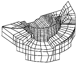
Structural analysis was performed on the structure using a three-dimensional
finite element model composed of 20-node iso-parametric brick elements
with three degree of freedom per node. Geometry for the design drawings.
The final model, which included the foundation, consisted of 2,790 nodes,
885 elements, and 7,047 independent equations.
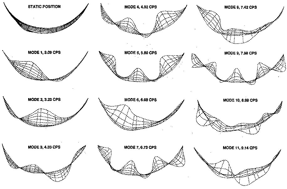
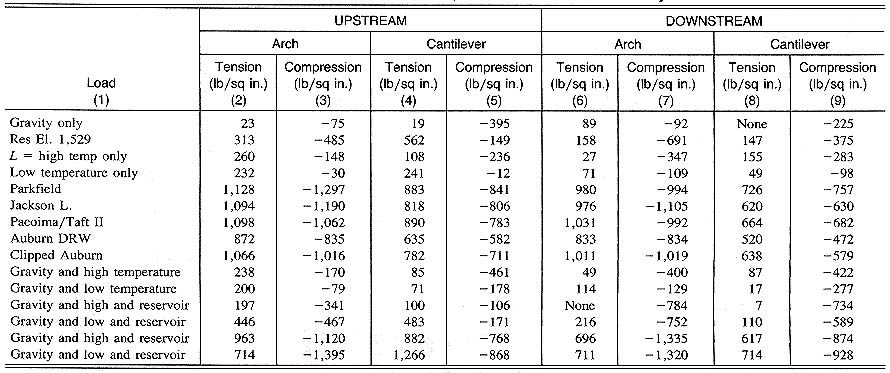
Results indicated a safe structure for normal operating and flood conditions, but an inadequate structure for earthquake conditions. At times during the earthquake, sufficient upstream movement of the arch develops simultaneous horizontal tensions at the same location on both the upstream and downstream faces. Note that concrete modulus of elasticity: static 2,200,000 lb/sq in. (15 GPa); dynamic 4,000,000 lb/sq in. (27.6 GPa). Foundation modulus: right 4, 000,000 lb/sq in. (27.6 GPa); wide fault 50,000 lb/sq in. (344.7 MPa); left 2,500,000 lb/sq in. (17.2 GPa). Dynamic MCE = Richter 6.75 at 15 km; scaled peak = 0.34 g upstream, 0.26 g cross stream, 0.17 g vertical, 10% damping, 11-mode superposition, 12.5 second records.
The vertical contraction joints could pull apart, eliminating the lateral support on the cantilevers. Sufficient upstream horizontal inertia force is developed in the top 40-60 ft (12.19-18.29 m) of the arch dam by the concrete and water mass to counteract the downstream normal reservoir force and the frictional resistance of the weak horizontal lift surfaces. This results in sliding instability of the concrete blocks.
MODIFICATION CONSIDERATION
Seismic analysis of the dam showed that the arch portion of the dam
is potentially unstable during a MCE seismic event. Justification of the
decision to modify the structure and the chosen method of modification
is based upon the following investigation findings.
Mather (1967) considered measures for prevention of deterioration. Replacing the entire dam was very expensive and not necessary considering the strong internal concrete. The interior dam material is in excellent condition except for the lift surfaces. The top portion of the dam, which may be subjected to the high inertia forces, could be totally replaced with current construction methods. This method, which would produce bonded horizontal joints in the top portion, was initially selected. A core sample, however, showed that all of the horizontal lift surfaces were unbounded. Sliding could occur just below the replaced portion. Also, concrete removal is an expensive process and would necessitate lowering the reservoir water level. Because water in Arizona is valuable, it was decided to modify the existing structure with minimal impact on the water supply.
Stability from sliding can be accomplished by reducing the driving forces or increasing the resisting forces. The driving forces on the concrete blocks due to inertia are induced by seismic loadings on the dam and reservoir. An earthquake imposes severe lateral loading and causes inertia forces on the concrete blocks. Basically, these forces depend on the relationship between the frequency content of the earthquake, the frequency of the dam could be altered by changing the mass or stiffness through the addition of concrete at optimum places. Some form of damping device could be added to increase the damping characteristics. These modifications were not investigated because of the difficulty of implementation, the likelihood of large costs, and the lack of precedents.
Components affecting resisting forces of the concrete blocks include friction and cohesion of the horizontal planes, strength of shear keys in the vertical joints, side constraints from the natural arching action of the dam, static reservoir load, uplift forces in the horizontal planes, and vertical earthquake motions. Existing block shear keys in the vertical contraction joints provide little resistance against sliding compared to the large inertia force produced by the blocks. The condition of the keys is also unknown. Upstream arch movements are resisted by the downstream reservoir component. Uplift from the internal pore pressure reduces the resisting force by unweighting the concrete blocks, thereby reducing the frictional component. Drainage within the arch to reduce uplift forces was not considered a viable solution because of the difficulty in constructing such a system.
Injections of epoxy resin or other adhesive were investigated for improving the cohesion or sliding resistance within the horizontal planes. A laboratory testing program was initiated in 1986 to investigate the increase in shear strength of a horizontal lift surface by injecting a methacylate compound (unpublished Bureau of Reclamation files, 1930-90). Tests were performed on actual lift lines from 6-in. (15.24 cm) cores extracted from the dam. Promising results were achieved in the laboratory. Concerns such as the repeatability in the field, injecting against full reservoir head, effectiveness in moist laitance coated joints, coverage or penetration in tight joints, quality control, verifying effectiveness, and estimating quantities terminated further consideration of the adhesive method.
The frictional resistance within the horizontal planes could be increased by post-tensioned cables or added weight. Adding weight to the dam was not considered because this harmfully increases the inertia forces at the top of the dam. Post-tensioned cables appeared the most viable and least expensive alternative for modifying the dam. The remainder of this paper deals specifically with the designs for post-tensioned cables.
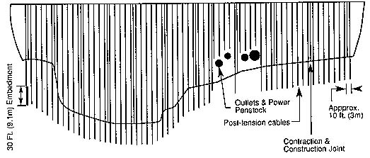
POSTTENSIONING
Post-tensioned tendons increase the normal force on the unbonded horizontal
arch lift line surfaces and consequently the frictional component of sliding.
Cables also produce three-dimensional stresses throughout the arch section
depending on orientation and eccentricities. Post-tensioning induces two
equal and opposite loads at the ends of the free length. Load at the top
or head transfers through the bearing plate into the concrete. This load
can be considered a concentrated, or point, force. Load at the bottom develops
through bond along the embedment length of the cable.
SLIDING STABILITY EQUATIONS
The Stewart Mountain Dam is an arch dam transferring load both vertically
and horizontally into the abutments. The dam is wedged into the canyon
by the natural arching action of the curved structure. An arch dam is efficient
as long as the arch stays together and the loads act downstream. Earthquakes
can develop loads detrimental to arch dams when seismic loads act in the
upstream or vertical directions. Natural arching action is lost once upstream
inertia forces counteract the downstream forces. Stability of individual
concrete blocks then becomes a two-dimensional sliding problem. The following
describes the components of this stability problem.
Driving forces in the upstream radial direction are due to horizontal earthquake induced inertia forces. These forces are influenced by: (1) Earthquake magnitude, distance, frequency content, and attenuation; (2) damping in the structure; (3) interaction of the natural frequencies of the structure and the earthquake; and (4) hydrodynamic interaction of the reservoir. Resisting forces are due to: (1) Friction within the horizontal lift surfaces (this friction is influenced by the weight of the concrete blocks, the unweighting of the blocks by the vertical earthquake motion, and the unweighting of the concrete blocks by uplift water pressures); (2)cohesion within the horizontal lift surfaces; (3) the downstream component of the static reservoir; (4) the natural arching action of the dam providing downstream restraint of the blocks; and (5) shear keys in the vertical contraction joints.
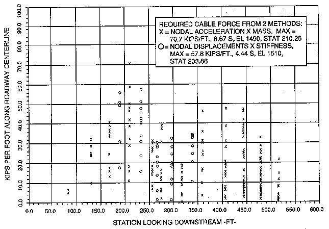
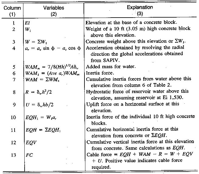
The following equations were used to calculate the required cable force
with a sliding factor of safety:
Equation
where FS = sliding factor of safety; W = static weight of block; EQV
= vertical inertia force of concrete; U = uplift (full at upstream, zero
at downstream); FC = required cable force if positive value; ? = static
sliding friction coefficient; C = cohesion of horizontal surface; A = area
of horizontal surface; SK = force developed in vertical contraction joints
from shear strength of keys and friction along the joint from horizontal
normal loads; EQH = horizontal inertia force of concrete; WAM = added mass
to simulate dam-reservoir hydrodynamic interaction (Westergaard 1931);
and R = horizontal hydrostatic reservoir force.
Solving for the required cable force yields the following equation:
Equation
As an example, assuming zero for cohesion (C), zero for the shear keys
(SK), 1.0 for sliding friction coefficient (?) and 1.0 for sliding factor
of safety (FS); Eq. 2 can be written
FC = EQH + WAM - R - W + EQV + U .(3)
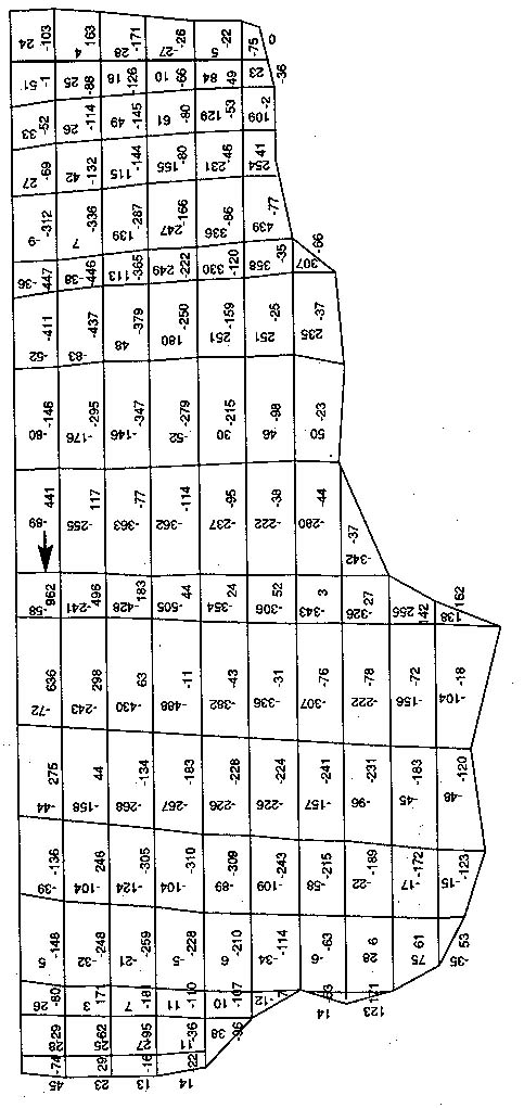
All the horizontal forces were transformed radial to the arch, measured perpendicular to the roadway centerline along the arch, and designated positive in the upstream direction. This permitted the calculation of inertia forces in the radial direction and showed that the concrete blocks would slide.
INERTIA FORCE INDUCED BY CONCRETE BLOCKS
Inertia forces of concrete blocks in the dam during an MCE had to be
calculated to determine the sliding factor of safety of the blocks. The
first factor that contributes to the inertia forces is the mass and acceleration
of the concrete blocks. The second contributing factor is the interaction
of dam and reservoir during the earthquake. Methods for calculating the
inertia force of the concrete blocks are described in the following.
Displacement X Stiffness Method (DSM)
One method for calculating the concrete block inertia forces during
the MCE is to use the final displaced shape of the structure and the stiffness
of the structure from finite element analysis, the basic premise being
Force = displacement X stiffness
.(4a)
F = K?
...(4b)
Dynamic analysis was performed by modal-superposition time-history methods. The finite element code calculated the final displaced shape of the structure for each time step during the earthquake. Inertia forces of an element were calculated in a post-processing phase with element nodal forces.
Westergaard's added mass was included in the analysis by lumping appropriate mass at the upstream nodes during the modal extraction phase. The final displacements included the effect of this type of approximation for dam-reservoir hydrodynamic interaction.
Mass X Acceleration Method (MAM)
Another method for calculating the concrete block inertia forces during
the MCE is to use the calculated mass for the blocks, the hydrodynamic
interaction, and the finite-element-calculated nodal block acceleration
blocks.
The basic premise is
Force = mass x acceleration
.(5)
The methodology for this approach is to compute inertia forces by multiplying the final finite element nodal accelerations at particular locations by the sum of calculated masses of 1 ft (0.305 m) wide concrete sections and of lumped mass contributions.
Comparison between DSM and MAM
The DSM and MAM methods for calculating concrete inertia force produced
very similar results with some differences worth noting. The computer inertia
forces did not compare exactly because of differences between the displacement
and acceleration curves, and differences between the modeled dam width.
The DSM method used displacements; the MAM method used accelerations. The acceleration curve is quite jagged compared with the displacement curve.
The width of the dam being investigated was quite different for the DSM and MAM methods. For DSM, each concrete block, ranging in width from 40 to 60 ft (12.2 - 18.3 m), was modeled by a single element. The MAM method used a 1-ft (0.305 m) wide section of dam. Displacements and accelerations vary considerably along the height and along the crest length of the dam. The DSM better represented the size of a concrete block and included the entire inertia force distribution within a block. The MAM method only included the accelerations at the upstream edge of an element, modeling only a small portion of the entire concrete block. For this reason the MAM method is considered only an approximate check of the DSM method.
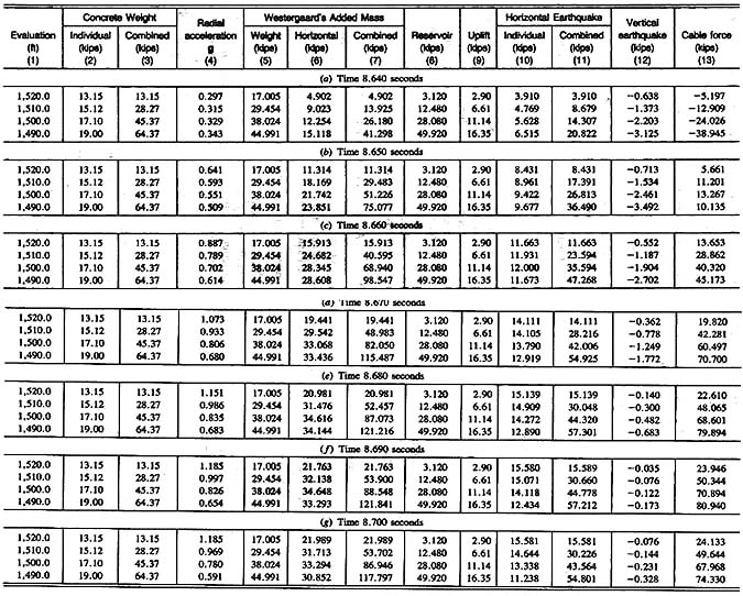
CABLE CAPACITY AND CONSIDERATIONS
The aforementioned inertia forces were computed at 15 locations along
the crest and substituted into Eq. 3. A design cable load is 700 kips (3,114
kN) pre 10 ft (3.05 m0 spacing along the crest. The cables were positioned
within the arch were as close as possible to the centerline of the vertical
radial section. Finite element studies showed a beneficial stress distribution
within the arch dam created by the cable load during normal operating conditions.
Special design considerations and requirements were developed for drilling
methods, drilling accuracy and tolerances, tensioning sequence, placement
within the arch, corrosion protection, grouting, monitoring, and pre-stressing.
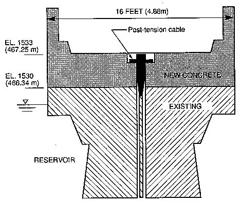
LOCALIZED CREST STRESSES FROM CABLES
Tremendous load enters the post-tension bearing plate, which must be
distributed into the arch dam crest. A 3-ft (0.194 m) thick reinforced
concrete overlay with formed blockouts houses the cable anchor head hardware.
Finite element studies were performed on a typical localized section of
the top of dam. Reinforcing steel was required to resist stresses developed
below the bearing plate and above the new and existing concrete interfaces
CONCLUSIONS
The Stewart Mountain Dam has been deteriorated by alkali-silica reactions
and exhibits no bond across horizontal lift surfaces. In addition, it is
now required to be subjected to an upgraded maximum credible earthquake.
Trends from historic deflection measurements, concrete coring programs,
and laboratory tests indicate that the deterioration from alkali-silica
reactions is contained. A system of post-tensioning for arch stabilization
was chosen. Ease of design and cable-load control were among the factors
in this selection. Post-tensioned cables are a viable solution for the
dynamic stability of a thin arch dam.
"Matilija Dam - Stress investigations." (1972). Report for the Department of Public Works, County of Ventura, International Engineering Co., Inc., Ventura, Calif.
Raphael, J. M. (1984). "Tensile strength of concrete," ACI J., 81(2), 158-165. "Railroad canyon dam safety evaluation." (1984). Final Report for TEMESEAL Water Company, Woodward Clyde Consultants, San Francisco, Calif.
Seed. H.B., and Idriss, I.M. (1982). Ground motion and soil liquefaction during earthquakes, Earthquake Engineering Research Institute, Berkeley, Calif.
"Seismo-tectonic investigation for Stewart Mountain Dam -- Salt River Project. Arizona" (1986). Seismo-tectonic Report No. 86-2, Bureau of Reclamation, Denver, Colo.
"Static and dynamic structural analysis of the arch, thrust locks, and gravity sections at Stewart Mountain Dam." (1987). Tech. Memorandum SM-220-01-87, Bureau of Reclamation, Denver, Colo.
"Structural designs of the post-tensioned cables for the dynamic stability of Stewart Mountain Dam, Phoenix, Arizona." (1990). Tech Memorandum SMC-3110-01, Bureau of Reclamation, Denver, Colo.
Von Thun, J. L., Roehm, L., Scott, G., and Wilson, J. (1988). "Earthquake ground motions for design and analysis of dams." Earthquake engineering and soil dynamics II: Recent advances in ground motion evaluation, geotechnical special publication no. 20, ASCE, New York, N.Y.
Westergaard, H. M. (1931). "Water pressure on dams during earthquakes."
Trans., ASCE, Paper No 1835, ASCE, New York, N.Y., 418-433.