The University of Texas at El Paso - Computer Science Department
CS 4390 - Building and Programming Mobile Robots, Spring 1999
| Robot Team #5 |
|
|

![]() Photo
Album: View our robot in action!
Photo
Album: View our robot in action!
The first three-four weeks the CS3490 class was being taught from the MIT 6.270 notes and from the Jones & Flynn "Mobile Robots" book. During the introductory four weeks, our robot team learned the basics about the mechanical aspects of robot building by constructing a robot body using Lego blocks. Adding a microprocessor board, sensors, motors making the robot autonomous, learning the microprocessor's programming language, experimenting with gear configurations, and sensor reading interpretations our team designed a mobile robot that would operate successfully on its own.
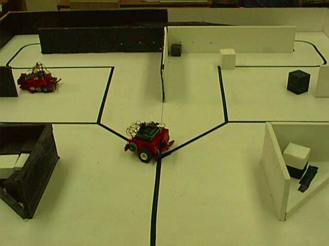
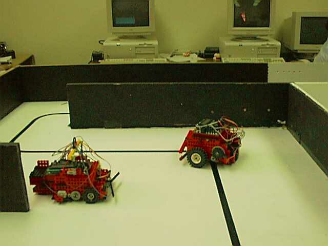
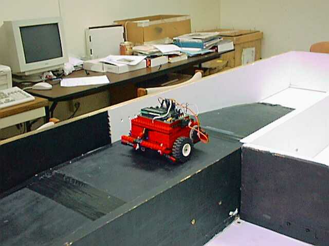
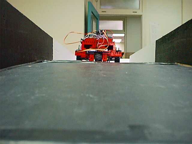
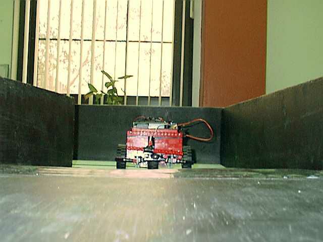
Our team spent the fourth and fifth weeks in formulating a strategy, and completing a robot that competed in a series of 4-5 tasks in a maze-like arena, (located in Computer Science Robotics Lab, at The University of Texas at El Paso.) Our robots tasks were of various degrees of complexity: from simple tasks such as following a straight line, climbing a slope, maneuvering through a maze, and getting to a destination in presence of unknown obstacles that were randomly placed throughout the maze course.
The final project our group
selected was adding artificial intelligence to our robot by software engineering,
simulating a "security patrol mobile robot." Our robot was able to learn
the layout of the maze-like course by detecting a path through a maze by
a series of bumper sensor readings. Once the robot had reached a target
area in the maze, a stop button would be pressed. The user was then prompted
with an option, on the robots LCD display screen, to adjust the speed
of the robot to run through the "learned" course on its own. Once the speed
was adjusted, the user only needed to press a start control bumper sensor
to begin the robots "learned" path through the maze.
Robot designed by: Ruben
Blanco & Marcus Dreeke
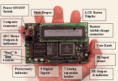
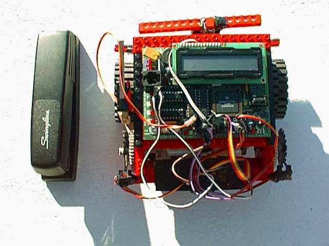
The "brain" of our robot was a 52-pin Motorola 6811 microprocessor, with a system clock at 2 MHz. Better known as the Handy Board it is a hand-held, battery-powered microcontroller board. The Handy Board was comprised with many components: a 32K of battery-backed CMOS static RAM, two L293D chips capable of driving four DC motors, two user-programmable buttons, one knob and piezo beeper, powered header inputs for 7 analog sensors and 9 digital sensors, internal 9.6V NICAD battery with built-in recharging circuit, hardware 38 kHz oscillator and drive transistor for IR output and on-board 38 kHz IR receiver, 8-pin powered connector to 6811 SPI circuit, expansion bus with chip selects allowing easy expansion using digital I/O latches, and a 16x2 character LCD display screen.
Ports and Connectors: The Handy Board
The body for our mobile robot had to be something strong enough to hold the Handy Board, but lightweight enough to allow adequate speed. Thus with the parts available we built our mobile robot out of Lego Technic advanced building blocks. The Technic Lego building blocks did a good job of housing the Handy Board, the motors, sensors, and bumpers were all easy to mount on the Robots Lego body.
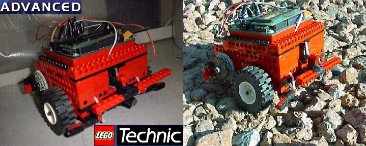
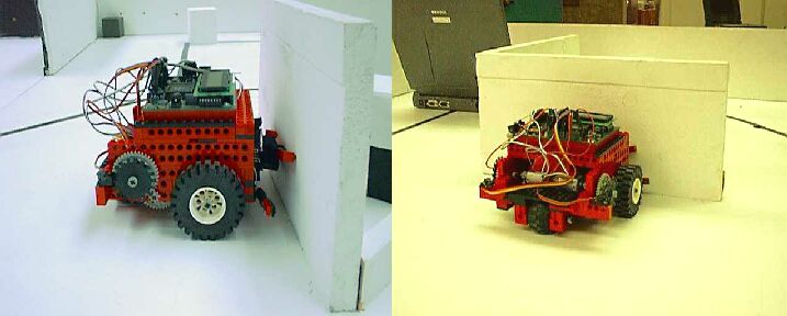
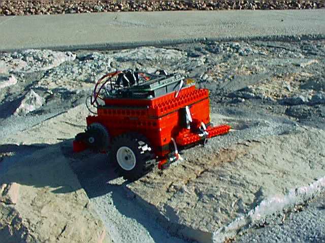
After many design configurations we decided upon a main body built around the Handy Board. The robot was built with three wheels: the front wheels being driven by the motors, and a free spinning (bubble-like) wheel in the rear. Each of the front wheels resides in a separate wheel compartment, containing their own drive motors and gear configurations. This design allowed the robot to be disassembled in three different sections, allowing us to adjust the gear configurations and replace a motor if necessary.
The room above the rear wheel existed to add additional components to the robot (such as an arm or other devices). Such a design similar to the cargo area (a small bed) of a pick-up truck.
In previous years, the UTEP
CS Building and Programming Mobile Robots course finished the semester
with a robotic competition. This competition was to design and implement
an operable robotic arm to the original mobile Lego robot. Such an arm
would grasp cube boxes and retrieve them to the robots starting point
(home base). We had this project in mind as we started designing our robot,
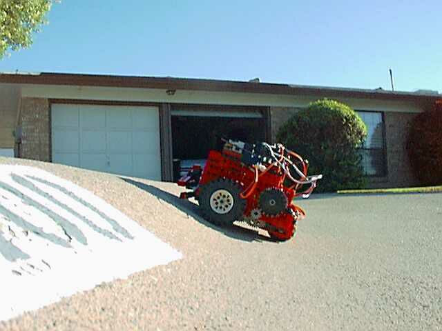
allowing additional room behind the handy board mount base. However, this
caused the robot to become off balance causing the robot to tilt when slowing
down and causing the robot unable to make it up the courses incline. We
were told to make the robot bigger, and add more weight to the robots
front end. Our team decided making the robot smaller and using less Lego
pieces to secure the robots body integrity would balance the robot. As
we changed our robots design once again, our reasoning proved true. The
Handy Board base was build around the processor. If we needed to add an
arm later, it could be easily mounted on to top of the rear wheel (as seen
in the above picture, the rear wheel mount is an extension to the main
body.)
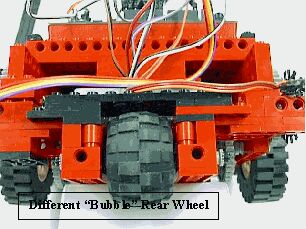
Our robot is front wheel driven by two 9 volt independent DC Motors, driving the two front wheels. The third wheel was a bubble shaped free spinning wheel centered in the rear. The 9 volt motors are both programmable to rotate their drive axis either clockwise (forward motion), or counter-clockwise (reverse motion). To turn the robot in the right direction the left motor is run forward, and the right wheel is run in reverse. To turn left, the left motor is ran in reverse and the right wheel is run forward. We originally wanted a caster wheel in the rear, however this design impeded our configured 180 and 90 degree turns. We found that with one wheel in the rear of the robot, allowed the 180 and 90 degree turns very easily and with a small turning radius. This proved to be a great design when maneuvering in the maze. Getting caught in a corner wasnt an issue for our robot. Our robots ability to turn in either 90 or 180 degrees was possible through using an infrared (IR) sensor device mounted on the front drives wheel configuration. We termed this IR configured device as "The Ticker" which will be explained in greater detail later. Steering the robot was initially obtained from Microswitch-style sensors (bumper sensors).
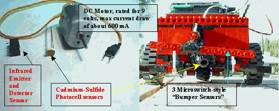
When a wall was hit the microswitch would return a signal to the processor. Depending on which bumper made contact with a wall, or object, this signal would indicate to the robot to execute a 90 or 180 turn (depending on its position in the maze and as dictated by our robots driving program). We later installed a photocell sensor underneath the main bumper to detect which side of the maze the robot was on, as indicated by the color of the wall as detected by the photocell.
We found that a combination
of microswitch-style and photocell sensors were effective control devices
to control such a robot through a maze-like course. However, the coding
of the Robots drive algorithm was lengthy when both sides of the course
were taken into consideration.
From the first trial project, running all the different robots designed in the class our robot was the fastest. Since our robot didnt depend upon reading the guideline throughout the maze with a photocell sensor we could make adjustments to our robots traveling speed. The robots dependent upon the guidelines were slow, due to the slow speed needed by the photocell sensor to detect the guidelines throughout the maze. Different lighting factors (from sunlight coming into the room through a window, shadows from people leaning into the maze, or even robot debris on course causing the path of the guide-line to change, etc.) further proved that the photocell sensors alone were not suffice to lead the robot through the maze.
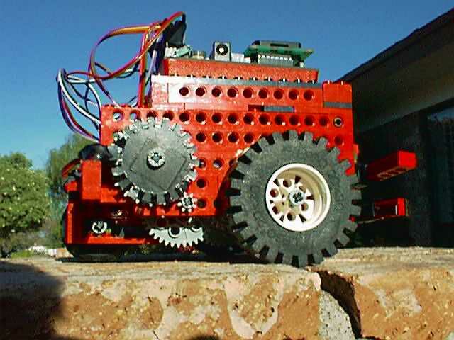
Gearing:
"Turn on a small DC motor, like the stock Lego motor, and what do you get? The shaft spins really fast, but with almost no torque (turning force). You can easily pinch the shaft with your fingertips and stop the motor from turning." Through gear reduction the fast-but-weak motor energy would have to be transformed into a strong and fast rotation to drive our mobile Lego robot. Designing such an effective gear train proved to be the most frustrating portion of the project. Designing such a gear train that would provide the most torque and power to drive the robot up an incline with the added weight of the Handy Board, and possible extra weight by carry objects was the portion of building the robot that took the most time. Building our first gear train we thought was adequate, proved to be inadequate through our testing and evaluations in the maze-course environment.
Proper "gear reduction is achieved by intermeshing gears of different sizes with compatible teeth." When meshing an 8-tooth gear with a 24-tooth gear "the 8-tooth gear rotates three times, advancing the 24-tooth gear one revolution. Hence producing a 3-to-1 gear reduction ratio More gear reduction can be achieved by meshing gears with greater disparities of teeth count. Using the Lego 8-tooth and the Lego 40-tooth gears produces a 5-to-1 reduction. But the more general solution is to gang together-or multiply- single pairs of gear reduction.1" This ganging together of single pairs of gear reduction is what we used for our robots main gear train.
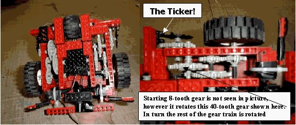
Keeping with the robots
component design, our team built two similar ganging of single pair gear
reductions for each front wheel being driven by a DC Motor. We configured:
a gang of an 8-tooth with a 40-tooth gear producing a 5-to-1 ratio, another
8-tooth with a 40-tooth gear producing a 5-to-1 ratio, then finally a 24-tooth
with a 24-tooth gear configuration producing a 1-to-1 ratio. Meaning approximately,
while the first 8-tooth gear rotates 25 times, the second gear level rotates
2 times, then finally the last gears rotate approximately one time. The
results we got from such a configuration were great! Through such a configuration
the robot was able to maintain a fast traveling speed (with a fresh, fully
charged battery) that was an advantage to our robot. Our robot had more
than adequate amount of torque to bang into walls, ram into other robots,
climb inclines with ease, and provide the ability to climb over small obstacles
making our robot a real winner!
Special Project, Team 6: Memorize Paths
Description: The robot moves forward until a bumper is hit, and turns to the side of the impact. Every time a bumper is hit, the robot memorizes its current location. This process is repeated until a button is pressed. Next, the robot should be able to go over its memorized path.
Solution: Our robot!
The first goal was, starting at a known origin, move to another part of the test field. Simple enough in theory, but we were dealing with a clean slate, a stupid machine. In analyzing the situation, it was determined that the easiest course of action to take would be to simply follow the walls of the maze until we reached the end. How do you get a Robot to follow a wall? We had two kinds of sensors at hand for this task: light sensors, and touch sensors. We had heard rumors of difficulty with the photocell sensor's accuracy, and it proved to be true in our tests. Our team decided to use the touch sensors, the bumpers to maneuver through the maze.
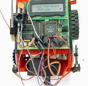
To get from any one point to another point, the shortest distance would be a straight line. Our robot did not quite have that luxury, with the many obstacles in the way. But we could break the task up into a series of straight lines that would lead the robot towards the ultimate goal, the finish line. The problem again was in which direction do you let the robot go, and for how long should it continue its path? Enter the TICKER!! We had access to an infrared sensor that had an emitter and detector, that were spaced by a small gap. The robot could be programmed to sense when something was placed between the sensor emitter and detector ports. This fact lead to the idea of placing one of the robots gears between the two sensor ports. That way, when the robot moved, the gear would spin, causing the gear teeth to block the IR sensor detector at a certain time, and not block it when the gear's teeth had cleared the IR sensor emitter between the sprockets. This would allow the processor to count the "ticks" as the wheel moved. So, no matter the speed of the robot (as is a problem when simply maneuvering the robot using time commands), we could get a fairly accurate distance on the robot by counting the number of ticks the gear moved. This proved to be detrimental in executing the robots turns. By simple testing, we determined the number of ticks to execute 90-degree turns. Now we had complete control of where the robot would travel through the maze. We could also use the ticker to move forward a pre-determined distance.
Now with bumpers on the front to tell the robot when it hit a wall, and the ticker to let it turn 90 degrees after hitting that wall, we simply had to put in the order of events to expect to get to the final goal. Not everything went perfect of course, but we did get to the top of the ramp as the problem stated. We weren't too happy with the accuracy of movement. With some fine-tuning of the software (making the tick subroutine detect both sprocket and blank space instead of just sprocket) and by constructing a custom gear with larger teeth to go between the sensor, we were able to greatly increase the control over the robot.
We created a new gear for the robot's ticker sensor, and it was cut out of a 1/6 polystyrene material on a sign plotter that was generally used to cut vinyl. It was designed so that the larger teeth would allow the sensor more time to count the ticks, because we realized that some of the smaller gear teeth were being missed because the gears were moving too fast. The number of ticks in the program had to be altered, but the increased accuracy was worth it.
With sub-routines to turn and go forward, we could execute any string of commands to get to one location to the other. Our programs either instructed the robot to go until it hit a wall, then turn, or go forward a set distance and then turn. This brought up an interesting thought. We were assigned to come up with a special project for our little robot to do. Would it be possible to teach the robot to get from one point to the other, without having to program it on the computer and upload it to the robot? We thought so!
It really didn't prove to be that difficult. In order to conserve memory, we limited the "learning" process to 25 steps, though we could have increased it if the task required it. Simply starting the process in a loop, the robot moved forward, all the while counting to itself how many ticks it's gone. Then on the users' touch of a left or right bumper, the robot would turn the according direction, and continue forward again. This was repeated until the programmer had reached the destination and stopped the machine with third bumper push. Then with the robot place back at it's original position, the tap of a button and off it went, following the same path just "taught" to it. Over and over the robot will do the same path until its' little wheels are too tired to move anymore.
In the limited about of
time we had, we were very pleased with the progress. Our robot not only
could execute a simple pattern, evade some obstacles (with the help of
a light sensor), and learn a pattern programmed on board, it was designed
so that the base commands were procedures that could easily be called to
help design any set of instructions desired. We knew there was room for
improvement. We definitely had a lot of speed on the little guy, but its
balance was sometimes off. It did hit the walls fairly hard, and we could
have put in light sensors to decelerate. There were little things that
would have to be fine tuned if the robot were going to be used for any
long term practical purpose. The biggest improvement that we knew we could
have made was adding a second ticker to another gear on the other side
of the robot. This would have allowed for a much more accurate response
to commands. Because we had two drive motors; the robot would often tend
to one side or another when driving a long stretch. The second ticker could
have been used to make sure both wheels were in sync. It would have also
made turns more accurate, like the times when it would stick on things
on the ground. The sum of the two wheels on the turn would make it always
turn the desired amount regardless of track conditions. If we were to continue
with the development of this robot, that would be the first improvement
we would make to it, knowing that it would be a more stable, controllable
system.
 |
 |
 |
 |
 |
 |
 |
 |
 |
 |
 |

Close up: The TICKER! |