Roland System 700 Analog Synthesizer Modules
7. Advanced Modulation Techniques
There are three primary modulation techniques available on all analog synthesizers: Ring Modulation (RM), Amplitude Modulation (AM), and Frequency Modulation (FM). Although the basic procedures vary with each technique, the primary objective of each is similar: to create complex source material for subtractive synthesis.
A. Ring Modulation
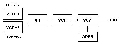
Ring Modulation is the only one of the three which requires a special module on the synthesizer: the Ring Modulator. This device has 2 inputs (often referred to as "X" and "Y"), a single output, and no manual controls. The inputs are regarded as identical, which means that signals present at the inputs could be switched without any difference in the result. The following diagram illustrates the incorporation of the Ring Modulator into a typical patch:

In Ring Modulation the output contains the sum and the difference of the frequencies present at the inputs. For example, if "X" were a Sine wave with a frequency of 100 cps. and "Y" a Sine wave with a frequency of 800 cps., the output would contain frequencies of 900 cps. (the sum: 800 + 100 = 900) and 700 cps. (the difference: 800 - 100 = 700).
Remember that this result would occur if each of the input waveforms were Sine waves. If any or both of the waveforms had harmonic content other than the fundamental pitch, sum and difference tones would be created with all of the harmonics present.
B. Amplitude Modulation
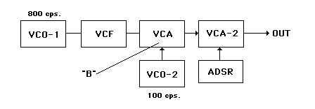
Amplitude modulation involves modulating the signal present at a VCA with an audible frequency VCO. The following diagram illustrates the incorporation of AM into a typical patch:

In this case the 2 VCOs are not considered equal in function.
VCO-1 provides a frequency (again an 800cps sine wave) which lies in the normal audio path. It provides the "carrier" frequency.
VCO-2 (again a 100 cps. sine wave) is set up to function as a control input to the VCA. It is considered the "program" frequency.
The result of AM, however, is very similar to that of RM. Again, frequencies are produced which are the sum and difference of the two VCO frequencies involved. But they are viewed in a somewhat different light: as a pair of "sidebands." Sidebands can be defined as frequencies produced above and below the carrier frequency at increments of the program frequency. They always occur as a pair, and AM always produces only one pair (if the 2 waveforms are sine waves). Thus in our example, sidebands are produced at 900 cps. ( 100 cps. above the carrier) and 700cps. (100 cps. below the carrier).
These are exactly the frequencies produced with RM, but in AM the carrier frequency itself is also present. Therefore, the final output contains 3 frequencies: 700, 800, and 900 cps..
Note that, in a sense, this modulation scheme does have an element which is variable: the amplitude of VCO-2 can be controlled at the input to the VCA (point "B" on the above diagram). Varying this control will change the amplitudes of each of the 3 resultant frequencies in relationship to each other, BUT it will NEVER change the frequency content. Note also that this type of modulation usually necessitates that a second VCA (VCA-2 controlled by the standard ADSR) be present as well. This is because the voltage contributed by VCO-2 will cause VCA-1 to sound continuously, even though no key is depressed.
C. Frequency Modulation
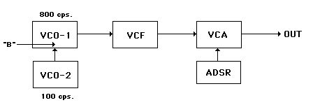
FM involves modulating the signal present at a VCO (VCO-1) with a second audible frequency VCO (VCO-2). As with AM, VCO-1 is considered the "carrier" and VCO-2, the "program" frequency. The following diagram illustrates the incorporation of FM into a typical patch:

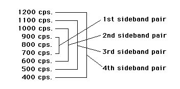
Similar to AM, FM results in both the carrier frequency and the production of sidebands. There is one very significant difference: changing the strength of VCO-2s output (again point "B" on the diagram) will result in varying the NUMBER of sideband pairs present. A stronger output will produce more sideband pairs.
As with AM, these pairs occur in increments of the program frequency above and below the carrier. In our example, the first pair of sidebands again occurs at 100 cps. above and below the carrier resulting in frequencies of 900 and 700 cps. If the signal is strong enough a second pair will be produced at frequencies which are 200 cps. (100cps. + 100 cps.) above and below the carrier resulting in frequencies of 1,000 and 600 cps. And so on: the number of potential sideband pairs is actually limited but also quite numerous. This phenomenon might be represented as follows:

---[ Home ][436 Information Index][Roland Index]---


